Technical Resources
How to Bleed Air from a Lubrication System
Air must be bled from lubrication lines whenever it is present. Incomplete bleeding can cause abnormal noise, vibration, corrosion and wear, resulting in insufficient or no lubricant delivery, reduced efficiency and possible failure.
Six common causes of air entering the lubrication system are:
Incorrect filling allows air into the system.
Vibration loosens pipe fittings, or damaged oil seals allow air into the system.
Ageing, cracked or excessively bent lines allow air into the system.
Low tank oil level or poor sealing of the suction line allows air into the system.
Disassembly during maintenance allows air into the system.
Air must also be removed after initial piping installation and before the first operation following a long shutdown.
Bleeding methods depend on the products in the lubrication system. The five main methods are:
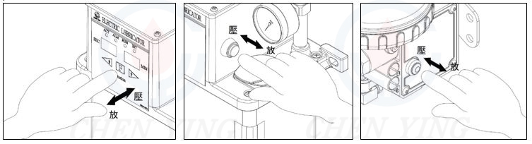
1. Lubricators with a manual lubrication button (F button)
Loosen the plug at the end of the line, then press the manual lubrication button intermittently to operate the lubricator. When oil flows from the line end without bubbles, connect the lines to the lubrication points.
Do not hold the manual lubrication button for more than 3 minutes, to prevent button damage and excessive motor heating. If the lubricator has motor thermal protection, operation stops when the motor reaches 100°C and resumes after a temporary stop of approximately 5 minutes.
2. Lubricators with an air-bleed device
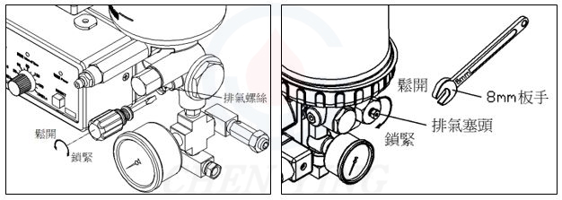
Loosen the air-bleed device counterclockwise and operate the lubricator. Watch for escaping air. Once oil flows without bubbles, tighten the bleed device clockwise, then connect the lines to the lubrication points.
3. Lubricators with a pressure-regulating valve
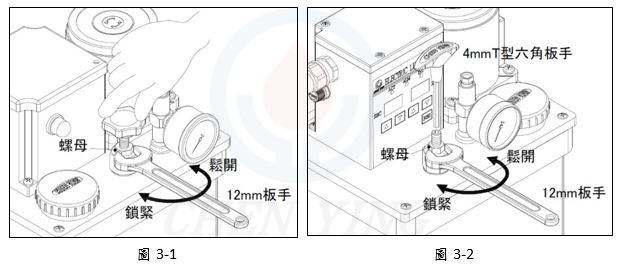
Two regulator types are used: a star handle with a locknut (Figure 3-1), or an adjusting screw with a locknut (Figure 3-2).
Loosen the plug at the line end. Turn the regulator locknut counterclockwise, then loosen the star handle or adjusting screw counterclockwise, using a 4mm T-handle hex key where applicable. Operate the lubricator and watch for air escaping below the regulator.
Once all air is removed, turn the regulator handle or screw clockwise while the lubricator operates until the required
pressure setting is reached. Tighten the locknut clockwise, then connect the lines to the lubrication points.
4. Pumps
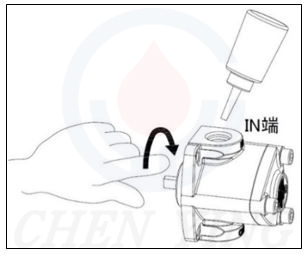
Add at least 20cc of lubricating oil to the pump inlet (IN), then turn the pump shaft clockwise by hand to draw oil into the pump and prevent dry running.
The inlet-pipe diameter must match the pump inlet or be one size larger. The inlet pipe must be no longer than 1m. Otherwise, bubbles may form in the line, causing noise, vibration and component damage.
5. Positive-displacement distributors
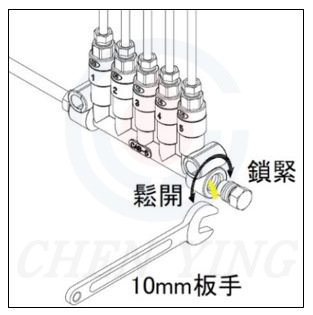
Connect the inlet line, then loosen the outlet lines or the plug at the line end. Fill the distributor with oil without pressure. When oil flows without bubbles, connect the lines to the lubrication points.
- Previous: CV Single-cycle Distributor: Structural Overview
- Next: Can Kytola Flow Meters Measure Different Media or Operate Under Conditions Different from Their Nameplate Ratings?
Latest News
- 2026-09-22 11:27:52
Recommended: Kytola SLM Smart Seal Water Flow Meter with 4–20 mA Output
- 2026-09-22 11:24:14
Variable area flow meters with 4-20 mA signal
- 2026-09-22 11:17:50
Let’s make your flow measurement Kytola Smart
- 2026-08-05 11:08:59
Kytola Gas Flow Conversion Formula
- 2026-08-05 11:03:07
Flow Meter Accuracy — Kytola, Finland
- 2026-08-05 11:01:20
How to Read a Kytola Variable Area Flow Meter