Technical Resources
CV Single-cycle Distributor: Structural Overview
The CV single-cycle distributor, also called a progressive distributor, works with oil or grease in resistance-type lubrication systems. Each outlet has a piston. Lubricant passes the first piston, then the second, and continues sequentially. One complete cycle dispenses lubricant once from every outlet.
Each CV distributor outlet delivers approximately 0.18cc as standard. Where a lubrication point needs a larger volume, we can combine outlets to increase delivery. Do not block any outlet yourself, as this prevents the CV distributor from dispensing correctly.
For example, when a CV-6 requires 5 outlets, the standard arrangement first plugs the outlet below the indicator rod (outlet marked 2; see the table below). If different outlet positions are required, specify them in advance or contact customer service. A standard CV distributor must retain at least one outlet on each side.
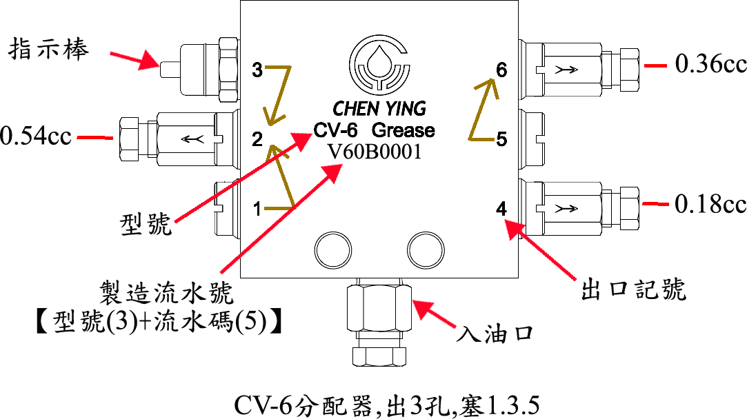
| Here.CV-6You know, distributor, for example. | Oil flow from the marked outlet. | ||||||
| Number of oil outlets. | Standard outlet plugging arrangement. | 1 | 2 | 3 | 4 | 5 | 6 |
| 5Hole | Plugged outlet mark.2 | 0.18cc | Plug | 0.36cc | 0.18cc | 0.18cc | 0.18cc |
| 4Hole | Plugged outlet mark.2、5 | 0.18cc | Plug | 0.36cc | 0.18cc | Plug | 0.36cc |
| 3Hole | Plugged outlet mark.1、3、5 | Plug | 0.54cc | Plug | 0.18cc | Plug | 0.36cc |
| 2Hole | Plugged outlet mark.1、3、4、6 | Plug | 0.54cc | Plug | Plug | 0.54cc | Plug |
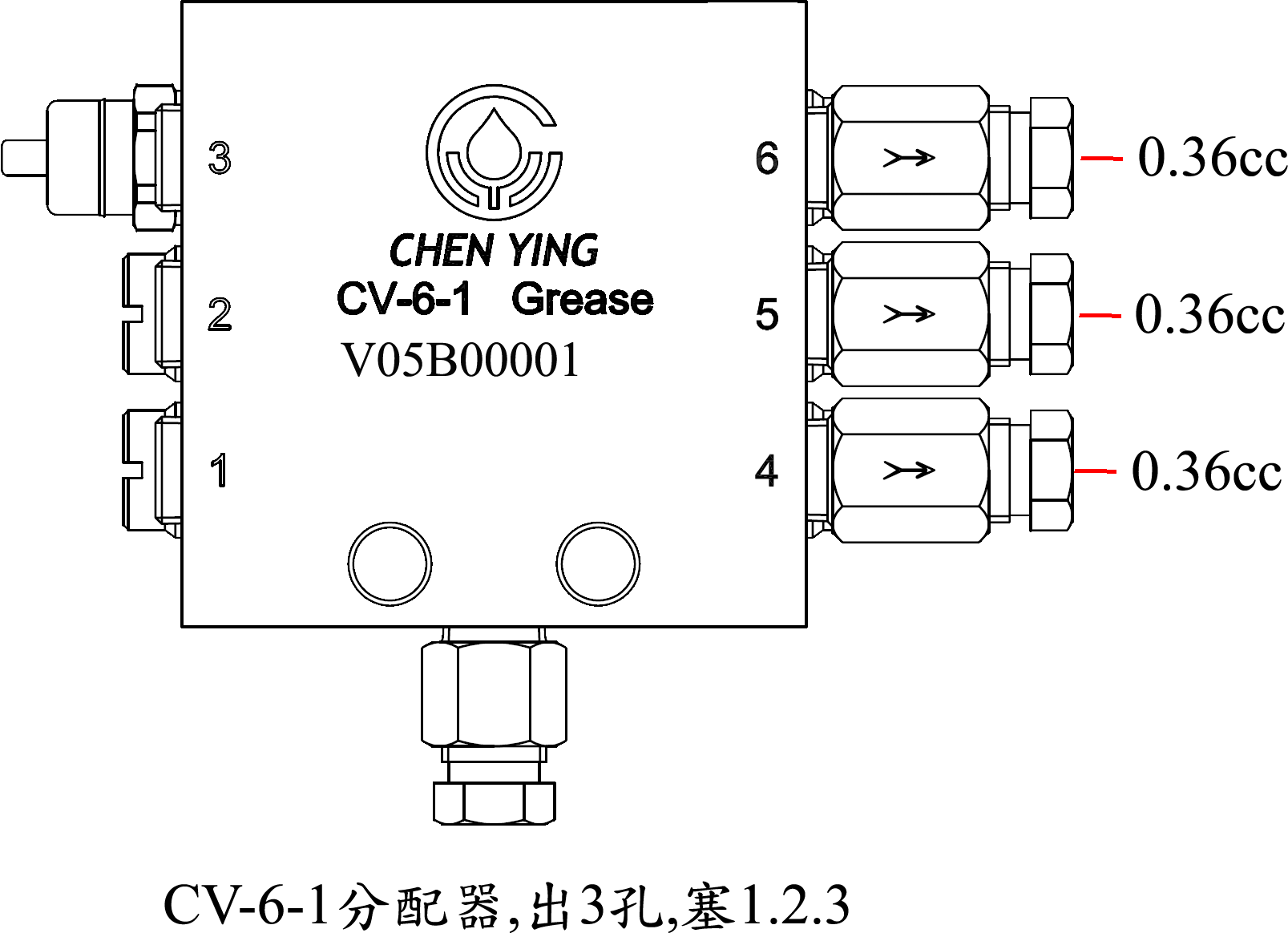
CHEN YING also offers CV distributors with interconnected left and right outlets: CV-6-1, CV-8-1 and CV-10-1. These 3 models currently have no ordering code; contact customer service if required. They are usually used as main distributors. For example, the CV-6-1 requires at least 3 outlets.
The diagram below shows a resistance-type grease-lubrication system. The lubricator feeds a CV-6-1 main distributor, with secondary distributors connected to lubrication points on the slideways. Because the secondary distributor models differ, the CV-6 has already entered its second cycle when the CV-8 completes one cycle.
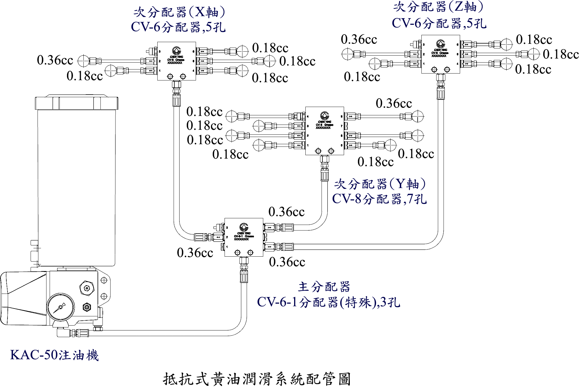
To choose a suitable grease reservoir, consider the total consumption at the lubrication points(Calculation method shown in the table below), together with the frequency of lubricant replenishment. Adding lubricant every three months is recommended to prevent deterioration beyond its shelf life and resulting damage to machine components or metal products.
X-axis CV-6 | Lubrication point. | 1 | 2 | 3 | 4 | 5 | 6 | Total flow. | |
| Flow rate | 0.18cc | 0.36cc | Plug | 0.18cc | 0.18cc | 0.18cc | 1.08cc | ||
Y-axis CV-8 | Lubrication point. | 1 | 2 | 3 | 4 | 5 | 6 | 7 /8 | Total flow. |
| Flow rate | 0.18cc | 0.18cc | 0.18cc | 0.18cc | 0.18cc | 0.18cc | Ser/0.36cc | 1.44cc | |
Z-axis CV-6 | Lubrication point. | 1 | 2 | 3 | 4 | 5 | 6 | Total flow. | |
| Flow rate | 0.18cc | 0.36cc | Plug | 0.18cc | 0.18cc | 0.18cc | 1.08cc | ||
Calculation: maximum total flow of the secondary distributors. * Number of main-distributor outlets=Total oil consumption. CV-8(Y Axis) 1.44cc * 3Hole =4.32cc | |||||||||
| Assumption1Total oil consumption per hour4.32cc;6hours per cycle;number of cycles24Hours/6Hours=4cycles,Therefore, total oil consumption4Times*4.32cc=17.28cc;Total oil consumption over three months17.28cc*90days=1555.2cctherefore,a 2000ccreservoir is recommended. |
- Previous: Differences Between Oil and Grease Lubrication Systems
- Next: How to Bleed Air from a Lubrication System
Latest News
- 2026-09-22 11:27:52
Recommended: Kytola SLM Smart Seal Water Flow Meter with 4–20 mA Output
- 2026-09-22 11:24:14
Variable area flow meters with 4-20 mA signal
- 2026-09-22 11:17:50
Let’s make your flow measurement Kytola Smart
- 2026-08-05 11:08:59
Kytola Gas Flow Conversion Formula
- 2026-08-05 11:03:07
Flow Meter Accuracy — Kytola, Finland
- 2026-08-05 11:01:20
How to Read a Kytola Variable Area Flow Meter