
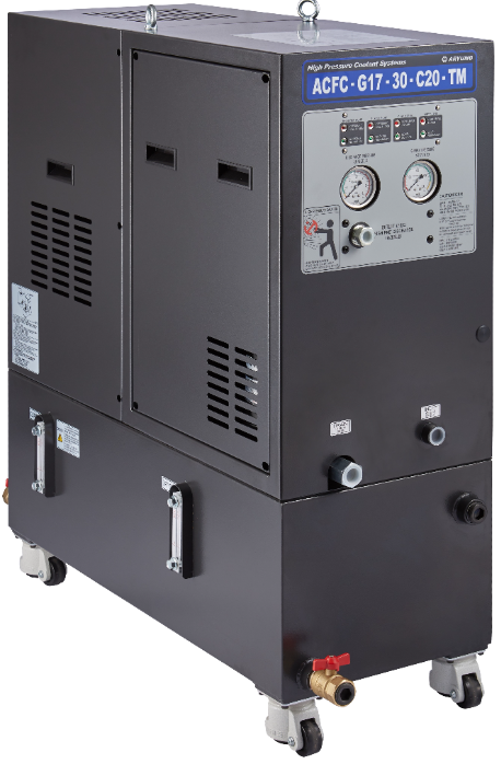
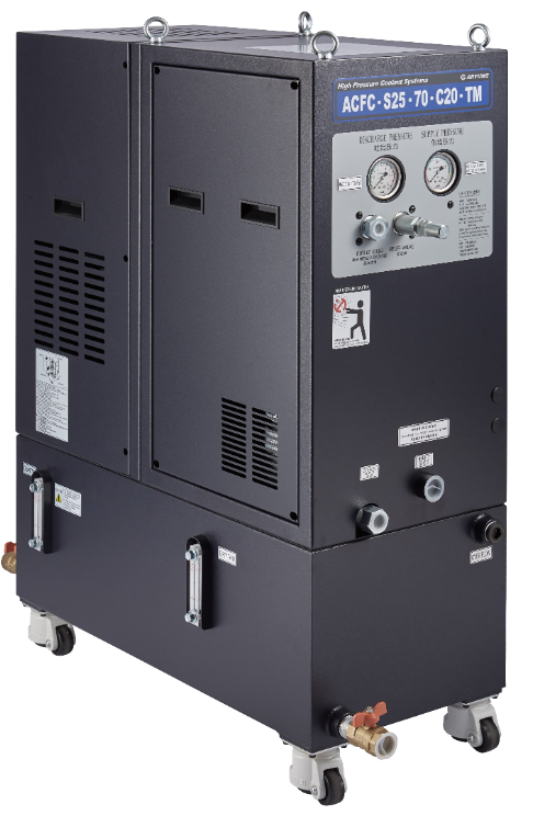
ACFC Series Cabinet Separate Unit A-RYUNG · Korea
Cabinet-type separate unit Cyclone filter: no replacement required
ACFC - S25 - 70 - C20
① ② ③ ④
① ARYUNG Coolant Filter Cabinet type system
② Pump Type
Gear pump ⇒ G17
Screw pump ⇒ S20 : AJ-200
S25 : AJ-250
③ Pressure
G17 ⇒ 20 : 20bar, 30 : 30bar, 50 : 50bar
S20 ⇒ 30 : 30bar
S25 ⇒ 70 : 70bar
④ Cyclone Filter Specification
C15 : ARCF-15B
C20 : ARCF-20B
C25 : ARCF-25B
I Product Features
• Cabinet-type separate unit
• High-pressure pump
Gear pump : G17 series
Screw pump : S20, S25
• Cyclone filter: no replacement required
Cyclone filter performance depends on the cutting material. Typically, approximately 95% or more of particles of about 10 μm–2 mm can be recovered without filter replacement, allowing long-term use.
• Dual-tank design: clean tank and dirty tank
• Built-in dirty pump: ACP-250F (150 L/min, 4 m head)
Forcibly discharges foreign matter from the dirty tank after cyclone filtration.
• Built-in discharge pressure gauge: 60 / 100 bar
• Discharge pressure switch: 2 bar
Detects high-pressure pump operation
• Built-in supply pump pressure gauge: 1–3.5 bar
• Optional supply pressure switch: 1 bar
Detects supply pump operation
• Built-in float switch: high-level ON (overflow alarm)
• Built-in relief valve: adjustment range 5–100 bar
• Optional LED indicators
LEDs indicate operating status
• Casters facilitate moving and installation
I Product Specifications
| Model Name | ACFC-G17-20 | ACFC-G17-30 | ACFC-G17-50 | ACFC-S20-30 | ACFC-S25-70 |
| Motor Power | 1.5kW/4P | 2.2kW/4P | 4.0kW/4P | 3.0kW/2P | 5.5kW/2P |
| Voltage(V) | 3Ø, 220/380, 50/60Hz | ||||
| Max. Flow rate [50/60Hz] | 23.0/28.0(ℓ/min) | 23.0/28.0(ℓ/min) | 23.0/28.0(ℓ/min) | 27.0/34.0(ℓ/min) | 35.5/44.0(ℓ/min) |
| Max. Pressure | 20bar/2.0MPa | 30bar/3.0MPa | 20bar/2.0MPa | 30bar/3.0MPa | 70bar/7.0MPa |
| Relief valve (Pre Range) | 5-70bar | 5-70bar | 5-70bar | 5-100bar | 5-100bar |
| Standard test Nozzle | Ø2.0(2.3ℓ/min) | Ø2.0(5.8ℓ/min) | Ø2.0(10.0ℓ/min) | Ø2.0(10.0ℓ/min) | Ø2.0(15.3ℓ/min) |
| Clean Tank | 27ℓ | 27ℓ / 140ℓ | 33ℓ | ||
| Dirty Tank | 27ℓ | 27ℓ / - | 32ℓ | ||
| Cyclone Filter | Built in | ||||
| Dirty Pump | ACP-250F - 250W | ||||
| Supply In-let | Rc 1" or 3/4" | ||||
| Discharge Out-let | Rc 1/2" | ||||
| Dirty Out-let | Rc 3/4" | ||||
| Drain or Over Flow | Rc 1" | Rc 2 1/2" | Rc 1" | ||
| Control Method | External control | ||||
| Supply Pressure Sensor | Option | ||||
| Discharge Pre' Sensor | Option | Option | Built in | ||
| Noise [dB(A)] | 80 under | 75 under | 80 under | ||
I Dirty Pump Specifications
| Model Name | ACP-250F | |
| Motor Power | 250 W | |
| Frequency | 50 Hz | 60 Hz |
| Power Source | 200V / 220V / 380V | 220V / 380V |
| Current | 1.5A / 1.4A / 0.87A | 1.6A / 0.93A |
| Discharge Volume | 120 ℓ/min | 150 ℓ/min |
| Head | 4 m | |
| Out - let | Rc 3/4" | |
I Recommended Supply Pump Specifications
| Model Name | ACP-1100HMFS 45 | |
| Motor Power | 1100W | |
| Frequency | 50 Hz | 60 Hz |
| Power Source | 200V / 380V | 220V / 380V |
| Current | 4.4A / 2.5A | 4.8A / 2.8A |
| Discharge Volume | 55 ℓ/min | 60 ℓ/min |
| Head | 20/25 m | |
| Out - let | Rc 3/4" | |
I Motor Specifications
| Out-put [ Kw ] | Frequency [ Hz ] | Poles [ P ] | Voltage [ V ] | Current [ A ] |
| 1.5 | 50 | 4 | 200 / 380 | 6.3 / 3.6 |
| 60 | 220 / 380 | 6.1 / 3.5 | ||
| 2.2 | 50 | 4 | 200 / 380 | 8.8 / 5.1 |
| 60 | 220 / 380 | 8.3 / 4.8 | ||
| 4.0 | 50 | 4 | 200 / 380 | 15.2 / 8.8 |
| 60 | 220 / 380 | 14.5 / 8.4 | ||
| 3.0 | 50 | 2 | 200 / 380 | 12.5 / 7.2 |
| 60 | 220 / 380 | 11.0 / 6.4 | ||
| 5.0 | 50 | 2 | 200 / 380 | 24.1 / 14.0 |
| 60 | 220 / 380 | 23.1 / 14.0 |
I Pressure / Float Switches (Optional)
| Discharge Pressure S/W | 0.5MPa | AC250V 1.7A DC32V 1.7A |
| Supply Pressure S/W | 0.1MPa | AC250V 1.7A DC32V 1.7A |
| Float S/W (Clean Tank) | Low Level ON | AC250V 0.33A DC200V 0.5A |
| Float S/W (Dirty Tank) | High Level ON | AC250V 0.33A DC200V 0.5A |
I System Front
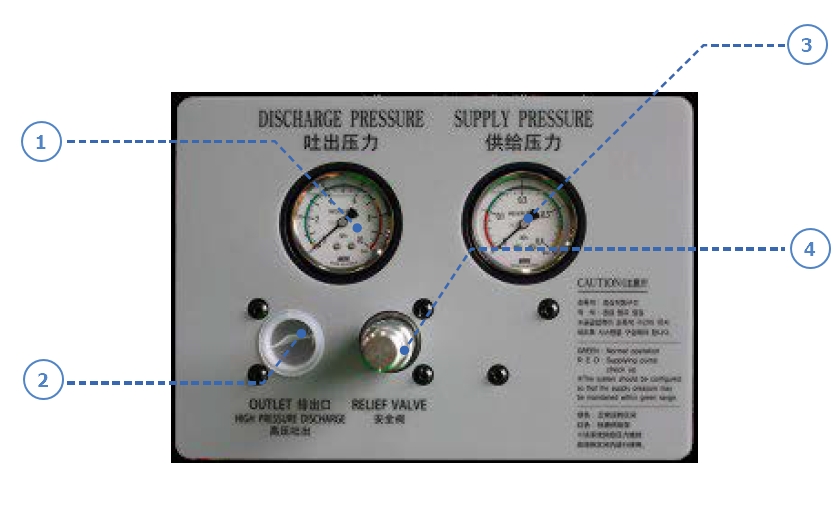
① Discharge Pressure Gauge
② Discharge Out-let
③ Supply Pressure Gauge Relief valve
• Maintain supply pump pressure within 1–3.5 bar
④ Relief valve
• Turn the cap left to remove it, then release the lock nut. Turn the adjustment bolt counterclockwise to decrease pressure or clockwise to increase it.
I LED Option System Front
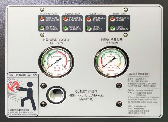
LED Indicators (Optional)
• Discharge (low pressure: below 2 bar)
• Supply Pump (low pressure: below 1 bar)
• Level Low(Clean Tank)
• Level High(Dirty Tank)
• Alarm output signal
• LEDs indicate operating status.
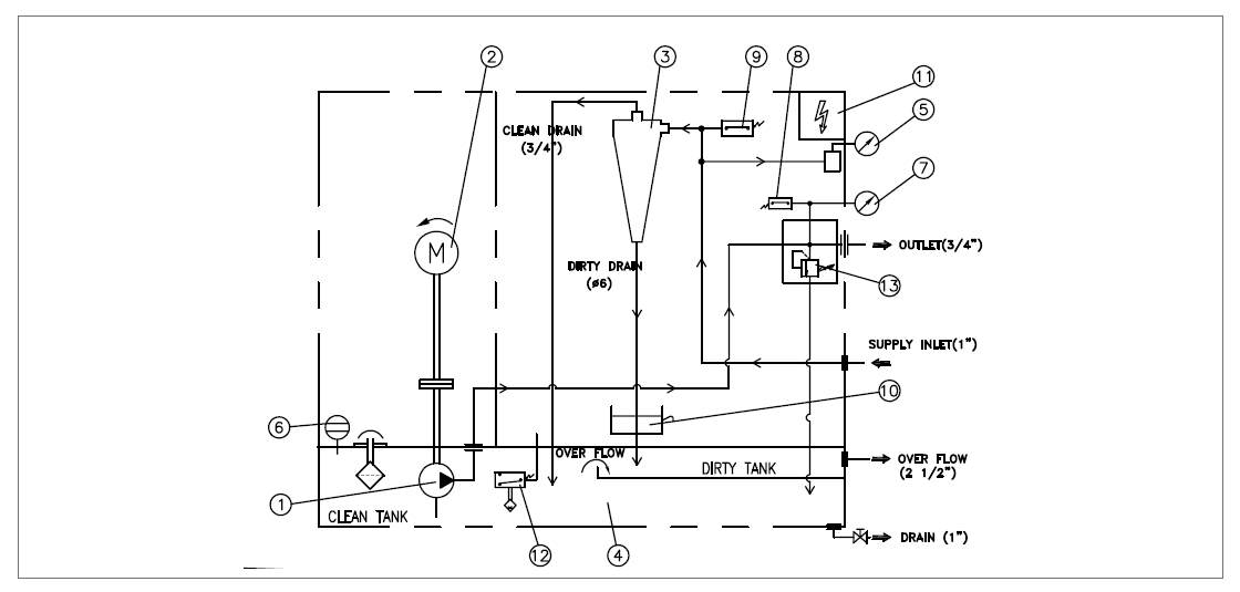
I Circuit Diagram
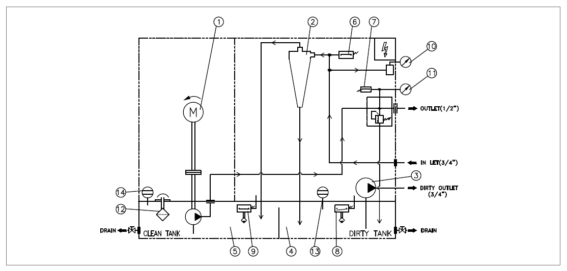
| No. | Component Names |
| 1 | High pressure pump |
| 2 | Cyclone filter |
| 3 | Dirty Pump |
| 4 | Dirty Tank |
| 5 | Clean Tank |
| 6 | Pressure Switch_Supply Pressure (Option) |
| 7 | Pressure Switch_High Pressure |
| 8 | Float Switch_Dirty Tank |
| 9 | Float Switch_Clean Tank |
| 10 | Pressure Gauge_Supply Pressure |
| 11 | Pressure Gauge_High Pressure |
| 12 | Air Breather |
| 13 | Fluid Level Gauge_Dirty Tank |
| 14 | Fluid Level Gauge_Clean Tank |
| No. | Component Names |
| 1 | SCREW PUMP |
| 2 | MOTOR |
| 3 | CYCLONE FILTER |
| 4 | CLEAN TANK |
| 5 | PRESSURE GAUGE |
| 6 | FLUID LEVEL GAUGE |
| 7 | PRESSURE GAUGE |
| 8 | PRESSURE SWITCH |
| 9 | PRESSURE SWITCH |
| 10 | CHIP BOX |
| 11 | CONTROL BOX |
| 12 | FLOAT SWITCH |
| 13 | RELIEF VALVE |
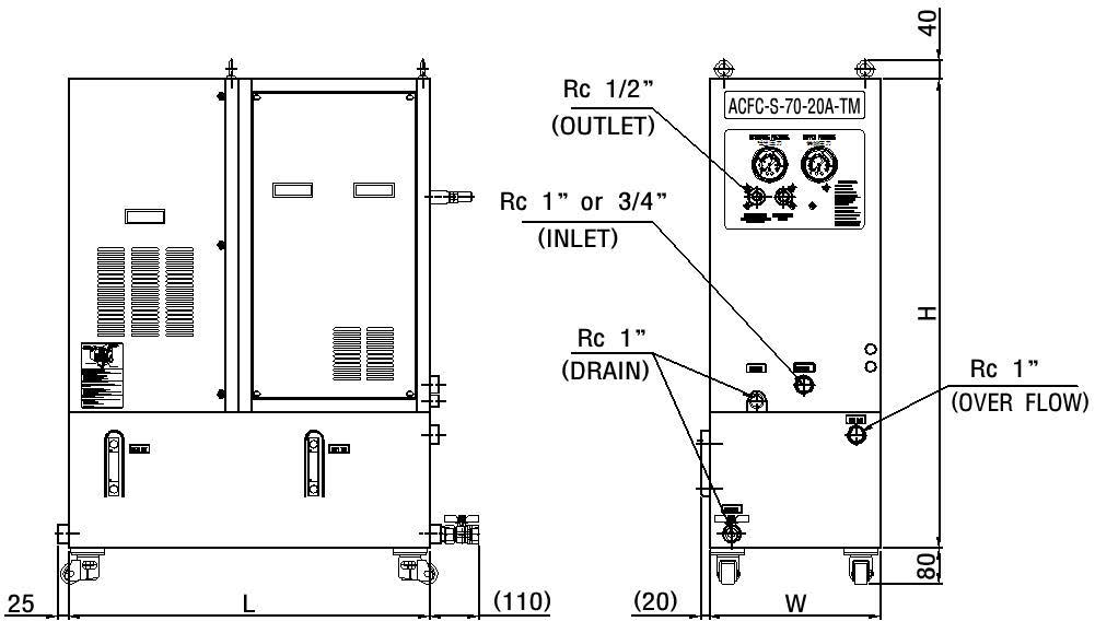
• ACFC -G17,S25
• ACFC-S20
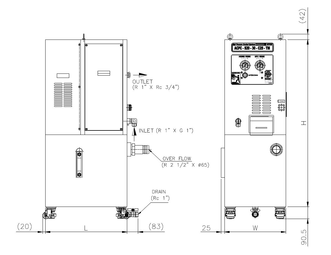
| No. | DIMENSION | |||
| W | L | H | OUTLET | |
| ACFC-G17/S20 | 380 | 860 | 970 | 1/2" |
| ACFC-S25 | 380 | 860 | 1040 | 1/2" |
| *ACFC-S20 | 450 | 600 | 1230 | 3/4" |
Note: ACFC-S20 has a clean tank only.
- Previous: ACFC Series Open Separate Unit A-RYUNG · Korea
- Next: ACFC Series Cabinet Separate Unit A-RYUNG · Korea
Related Products
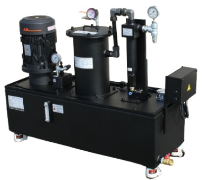
ACFC Series Open Separate Unit A-RYUNG · Korea
ACFC Series Cabinet Separate Unit A-RYUNG · Korea
ACFC Series Cabinet Separate Unit A-RYUNG · Korea
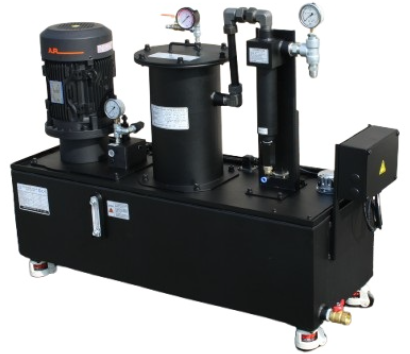
ACFC Series Open Separate Unit A-RYUNG · Korea
Related Services / service
Regional Products / city
- Anhui — ACFC Series Cabinet Separate Unit A-RYUNG · Korea
- Beijing — ACFC Series Cabinet Separate Unit A-RYUNG · Korea
- Chongqing — ACFC Series Cabinet Separate Unit A-RYUNG · Korea
- Fujian — ACFC Series Cabinet Separate Unit A-RYUNG · Korea
- Gansu — ACFC Series Cabinet Separate Unit A-RYUNG · Korea
- Guangdong — ACFC Series Cabinet Separate Unit A-RYUNG · Korea
- Guangxi — ACFC Series Cabinet Separate Unit A-RYUNG · Korea
- Guizhou — ACFC Series Cabinet Separate Unit A-RYUNG · Korea
- Hainan — ACFC Series Cabinet Separate Unit A-RYUNG · Korea
- Hebei — ACFC Series Cabinet Separate Unit A-RYUNG · Korea